
Your RTO Panel Reads 1,500 F. Your Stack Test Says 50 Percent. Both Can Be True.
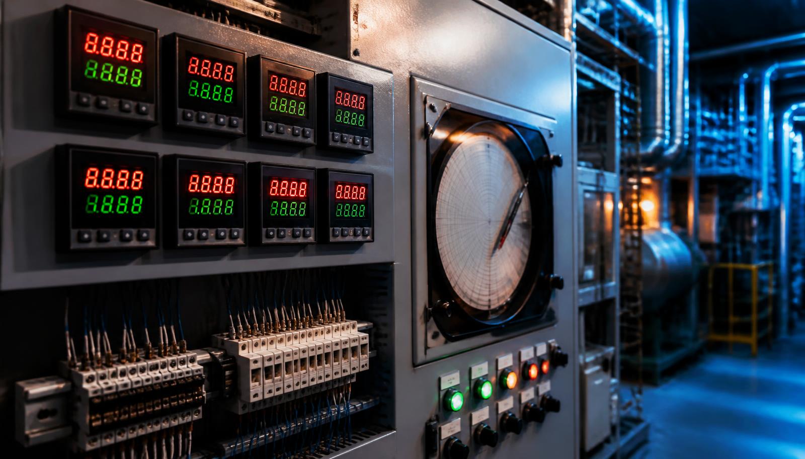
There is a particular kind of bad day in air abatement. The stack test comes back at roughly half the destruction efficiency your permit requires, and nobody can explain it, because the control panel says the oxidizer has been sitting at temperature the entire time.
Maintenance checks the burner. It fires. Operations checks the trends. They are flat and stable. The chamber temperature on the HMI reads exactly where it is supposed to read. Every instrument in the building agrees that the unit is healthy, and the lab result says it is not.
Both are telling the truth. The instruments are reporting faithfully. They are just reporting a number that was calculated wrong three steps upstream.
How a temperature reading gets manufactured
On most regenerative thermal oxidizers, the number you see on the HMI is not a direct measurement. It is the end of a chain.
A thermocouple in the combustion chamber produces a few millivolts. That signal usually lands in a safety limit controller, which does its own job (independent high limit protection) and then retransmits an analog copy of the temperature to the PLC, commonly as 4 to 20 mA or 1 to 5 VDC. The PLC scales that analog signal back into engineering units. The HMI displays whatever the PLC calculated.
Two separate configurations have to agree for that math to work. The limit controller has a retransmission span, the range of temperature it maps across its analog output. The PLC has an input scaling range, the range it assumes when converting that analog signal back into degrees.
When those two ranges match, the number is right. When they do not, every reading on the unit is wrong by the ratio between them, and it is wrong quietly.
The arithmetic of a quiet failure
Say the limit controller is spanned 0 to 1,600 F and the PLC input is scaled 0 to 2,400 F. The ratio is 1.5. Every temperature the PLC calculates is one and a half times the real value.
An actual 1,000 F chamber displays as 1,500 F.
Now follow what the control system does with that. The temperature control loop sees 1,500 F, decides the chamber is comfortably at setpoint, and backs the burner off. The burner under fires. The chamber settles even further below where it needs to be. The panel continues to show a stable, correct looking number, because the error is proportional and the display tracks the setpoint beautifully.
The direction of the error is what makes this dangerous. A false low reading causes over firing, which wastes gas and eventually trips a high limit, and somebody notices. A false high reading causes under firing, which produces no alarm, no trip, and no complaint from the equipment. It just quietly destroys fewer VOCs.
Thermal destruction is not forgiving about temperature. Run a few hundred degrees below your design chamber temperature and destruction efficiency does not degrade politely, it falls off. That is how a facility ends up failing a stack test at what the panel insists is normal operation.
Why nobody catches it
This failure mode hides better than almost anything else in a thermal system, for four reasons.
No alarm fires. The value stays inside its valid range. Nothing is broken, out of band, or reading upscale burnout. Alarms catch signals that fail. They do not catch signals that lie.
The trend history looks perfect. Because the error is a fixed multiplier, historical trends are smooth and internally consistent. There is no step change to point at, no drift, nothing that looks like a fault.
Operators trust the display, correctly. They have no reason not to. This is not carelessness. The instrument they were given is telling them a specific number with two decimal places of confidence.
The drawings are still right. The as built package documents the original design, and the original design was almost certainly correct. The mismatch was introduced later.
It almost always arrives with a change
Span mismatches are not born, they are installed. Look for the event.
A limit controller gets replaced and the new one ships with a different default retransmission range. A PLC program gets reloaded from a backup that predates a scaling change. An analog card is swapped. A panel gets repaired after a lightning strike or a power surge and several components come back with factory defaults. Somebody upgrades one half of the loop and reasonably assumes the other half already matched.
If a facility has had a significant electrical event, a controls repair, or a program reload since its last passing stack test, the instrument scaling deserves a look before the next one. If the test has already come back bad, the first 30 days after a notice of violation are the wrong time to be discovering this for the first time.
How to check it in an afternoon
You do not need special equipment to find this. You need four numbers and a willingness to distrust the screen.
- Read the same temperature at every stage at the same moment. The field limit controller's own display, the PLC's raw analog input count, the PLC's scaled value, and the HMI indication. Write all four down. If they diverge by a consistent ratio rather than a consistent offset, you have a span mismatch, and the ratio tells you which two ranges disagree.
- Read the actual configuration, not the drawing. Pull the retransmission span out of the limit controller's parameters and the input scaling out of the PLC logic. The drawing tells you what was designed. The configuration tells you what is running.
- Do a documented simulator check. Inject a known signal in place of the thermocouple and confirm the value at every stage of the chain. Do it before the next compliance test, not after the next failure, and keep the record.
- Use the second measurement path if you have one. Many oxidizers measure combustion chamber temperature twice by original design, once for control and once for independent high limit protection. Two paths that disagree is a free diagnostic, and it costs nothing to compare them.
- Verify thermocouple type per channel. Do not assume a unit is uniform. Mixed Type J and Type K on the same oxidizer is common in original designs, with the chamber on one type and the recovery beds on another. A channel configured for the wrong type is a second, independent way to get a confidently wrong number.
- Do not stop at the temperature loop. While the panel is open, confirm that combustion air and process airflow are actually proven rather than inferred. Drive run status and commanded speed are not proof of airflow.
The bigger question underneath
Sometimes a scaling mismatch is a simple fix, corrected in an afternoon, and the unit goes back to work.
Sometimes it is a symptom. If the oxidizer is running a discontinued PLC platform, a general purpose PC standing in for a failed operator terminal, an obsolete drive on the main blower, and limit controllers that are no longer manufactured, then the scaling error is not really the problem. The problem is that every future repair will be like this one: a component that cannot be replaced like for like, a setting that comes back at a factory default, and a system nobody can fully validate.
At that point the honest answer is not another patch. It is a coordinated control panel modernization, where the PLC, operator interface, blower control, temperature protection, and safety interfaces get replaced and commissioned together, with the sequence documented and the analog paths validated end to end. One planned outage instead of an indefinite series of unplanned ones. That work sits inside our service and upgrade scope.
The takeaway
A control panel is not a measurement. It is a calculation, performed on a signal, using assumptions somebody configured. When those assumptions drift out of agreement, the panel will keep reporting with total confidence, and it will be wrong in the one direction that produces no alarms and no complaints.
If your oxidizer is failing emissions performance while the panel insists it is at temperature, do not start by doubting the lab. Start by validating the signal chain.
CREATE Industries performs thermal oxidizer diagnostics, instrument and analog path validation, controls troubleshooting, and control panel modernization on industrial combustion systems nationwide, through CR8 Environmental.
Frequently Asked Questions
How can an RTO read at temperature and still fail a stack test?
The number on the panel is a calculation, not a measurement. If the limit controller's retransmission span and the PLC's input scaling do not match, the PLC converts the analog signal using the wrong range, and every displayed temperature is off by the ratio between the two ranges.
Why does a false high reading cause more damage than a false low one?
A false low reading causes over firing, which wastes fuel and eventually trips a high limit, so somebody notices. A false high reading causes under firing, which produces no alarm and no trip. The chamber quietly runs cooler than required and destroys fewer VOCs.
What usually causes a span mismatch?
A change. A replaced limit controller shipping with a different default retransmission range, a PLC program reloaded from an older backup, a swapped analog card, or a panel repaired after a lightning strike where components came back at factory defaults.
How do I confirm the temperature reading is real?
Read the same temperature at every stage at the same moment (field controller display, PLC raw count, PLC scaled value, HMI), then compare the actual configured spans rather than the drawings. A documented simulator check with a known injected signal confirms the whole chain.
When is a scaling fix not enough?
When the oxidizer runs a discontinued PLC platform, obsolete drives, and limit controllers that are no longer manufactured. At that point the scaling error is a symptom, and a coordinated control panel modernization is the honest answer.
Failing a Stack Test Your Panel Says You Should Be Passing?
Get in touch, or call 24/7 emergency service at (251) 209-8127.
Talk to an Engineer